This build is a 3-axis CNC (Computer Numeric Control) router with a large table area. The table is intended to accept most of a 4' x 8' sheet. If we ever decide we need a longer table (i.e. for an entire 4' x 8' sheet) then we can easily expand the length axis. We wanted decent precision and accuracy while still being able to maintain speed of the machine. We opted for a ballscrew drive, even though the length of the long axis is considerable, because we wanted to maintain the precision. To control whip of the relatively small 16mm diameter ballscrew over the length, we ensured that the precision of the machining on this axis was exceedingly accurate, then made further adjustments based on response and speed once the machine was assembled. By also cutting back the maximum feed rate for this axis, we limited the whip movement of the ballscrews. We opted for two drive systems on the long axis because of the size of the machine, slaving the two together in the software.
We decided to use limit sensors on each axis to prevent accidentally crashing the machine at the axis limits. These sensors communicate with the software and halt axis movement when triggered at either end. They can also be used to 'home' each axis in the software. The Z-axis only uses one sensor at the top, because different length mills would change the lower end too much to make any long-term calibration useful.
The table is designed to use a spoil board as we intend to do some cutting completely through the material. The actual table is 3/4" MDF, with a 1/8" hardboard spoil sheet on top that can be easily replaced as necessary when it becomes too battle scarred for further use. We intend to use toggle clamps along the edge of the table to restrain the target material, as we do not want to fuss with a vacuum system at this point.
The spindle is a standard router with a 90mm diameter barrel, clamped onto the Z-axis. The spindle speed is regulated by a 120v rheostat on a dedicated control box, while spindle power is switched through a computer-controlled relay.
The overall design is a scaled up version modified from a smaller initial design done by machinist Brian Brant out of Delaware. We made some adjustments based on our requirements, as well as some modifications for longevity and higher precision. We also made some minor overall improvements throughout for use in a large shop environment. It is a fairly scaleable and modular design, so adjustment can be made for similar but different sized machines.
In this run-through, we don't intend to go through the nitty-gritty basic stuff like what screws we used, or how we soldered connections. This is mostly intended as a general guide illustrating that it really isn't that hard to build one of these machines with the proper tools, time, and patience to do things right. There's lots of general information out there on the internet in building CNC machines, so we thought we would supplement that with a (mostly) complete build description, and hopefully some tips and tricks we gathered along the way during the overall build.
We chose Mach 3 software, as a complete version is very affordable and would fit our requirements. We purchased a dedicated older Windows XP desktop machine as Mach 3 does not run on newer software (at least, at the time of this writing). The computer communicates with the contol box through a standard parallel cable and into a breakout board in the controller. We opted to mount the control box under the table of the machine, meaning only the parallel cable and a power cable would need to run from the general area of the machine. The control box connections use aviation style 16mm connectors for durability and ease of use.
Because this machine was intended for use in a dusty shop environment, we built (albeit quickly from what we had on-hand) a separate, sealed computer cabinet with a filtered, forced air circulation system. Everything except the wireless keyboard and mouse are inside the enclosure, and these are easily cleaned and/or replaced if necessary. We built the same fan/filter system into the control box so that only periodic filter cleanings are necessary to keep the unit safe and internally clean.
A quick CAD model of the design was very helpful (but not necessary) so that we could more quickly arrive at our measurements and dimensions.
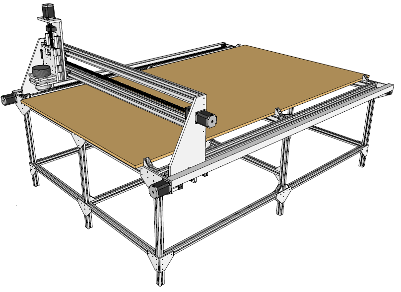
This parts list was selected according to our specific predicted needs, motor torques, etc. Obviously depending on the use of the machine, these parts could be upgraded (for durabilty) or downgraded (to save money).
--------
Basic parts breakdown:
-80/20 Inc. T-slot aluminum extrusions, plates, and brackets for the basic framework. We used 3030 series (30mm X 30mm) in this case.
-(4) NEMA 23 stepper motors, single shaft, 425 oz. in. torque (23HS9430).
-(4) Drivers: DM542A, peak 4.2A, 128 microsteps.
-(2) 350 Watt, 36 VDC / 9.7A power supply, each running two motors/drivers.
-SBR16 fully supported ballscrew guiderails, various lengths to match appropriate axis (16mm dia.).
-RM1605 ballscrews, various lengths to match appropriate axis (16mm dia.).
-BF12 / BK12 bearings and blocks for ballscrews.
-1/2" thick aluminum plate for machined gantry ends (Y-axis), router carrier, and Z-axis.
-3/8" thick aluminum plate for machined X-axis ends, and other small parts.
-(5) Inductive proximity sensor switch, NPN NO+NC DC6-36V LJ12A3-4-Z/CX.
-Emergency stop switch, resettable.
-(3) 120v status lamps.
-(2) 120v toggle switches.
-Fuse holder, 120v, 15A.
-(1) standard computer 120v female outlets.
-(2) standard computer power supply 120v male outlet.
-(2) standard computer power supply 120v cords.
-Sensor relay board/module for inductive sensors, 4 channel, with 12 VDC power supply (SRD-12VDC-SL-C).
-Parallel cable with breakout control board, and 5 VDC power supply.
-22awg/4c shielded stranded wire cable (for motors and sensors).
-1/16" plate aluminum for controller box (80/20 T-slot used for controller box frame).
-Solid state relay, PC 24-380 VAC, 25 AMP, 3-32 VDC input (control router on/off).
-Aluminum relay heatsink (for above), 1.5 degrees C/Watt.
-1/2" aluminum tube stock, cut to length for bearing block stand-offs.
Relatively speaking, there is not a lot of custom machining necessary for a machine like this. There are the gantry end plates, the Y-axis end plates holding motors and ballscrews, and the Z-axis plates. Even these can be purchased, but where's the fun in that? So we whipped up a set in the shop.
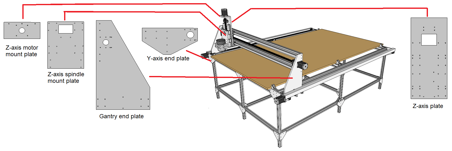
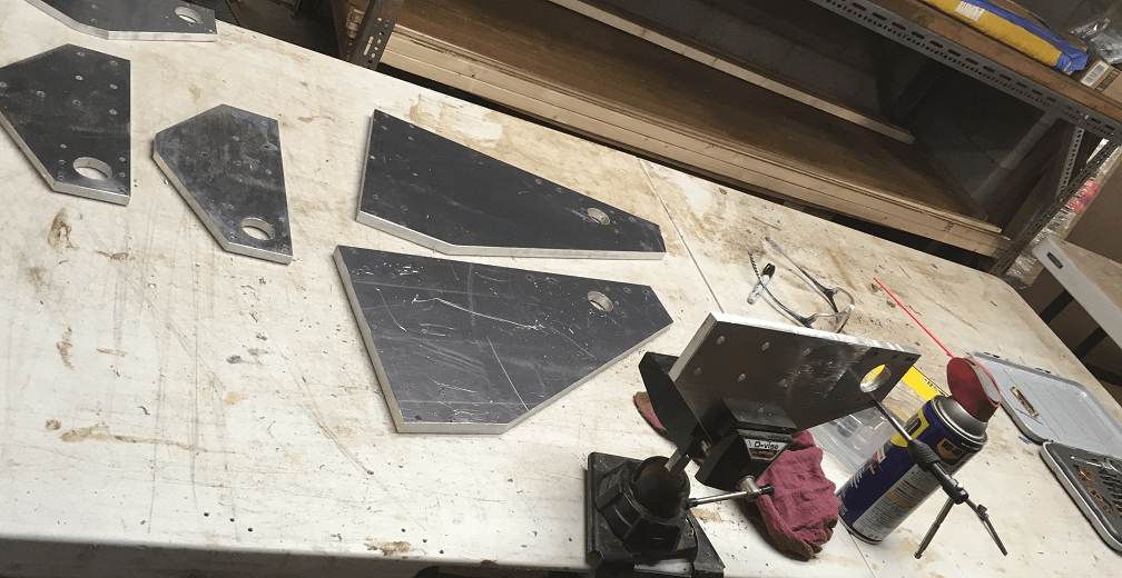
Before committing these parts to machining, we measured, checked, and then milled wooden test articles since we've got lots of scrap wood around. Then we made further adjustments if necessary and machined the final plates since large sheets of thick aluminum are fairly expensive. We had the advantage of being able to mill these on our other CNC equipment, but it may just as easily be completed by manual machining. There aren't that many pieces that require machining, but they must be precise and exact no matter what method is used. The precision of these plates controls the alignment of the motors and ballscrews, as well as the alignment with the guiderails.
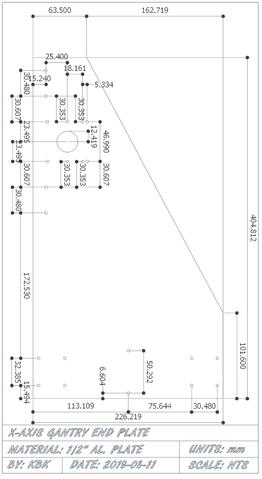
Link to .DXF file ready for conversion to g-code, containing all these plates: CNC plates.dxf


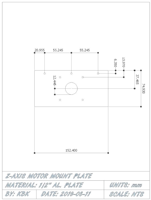
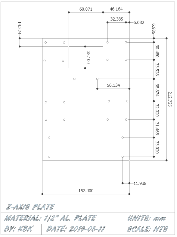

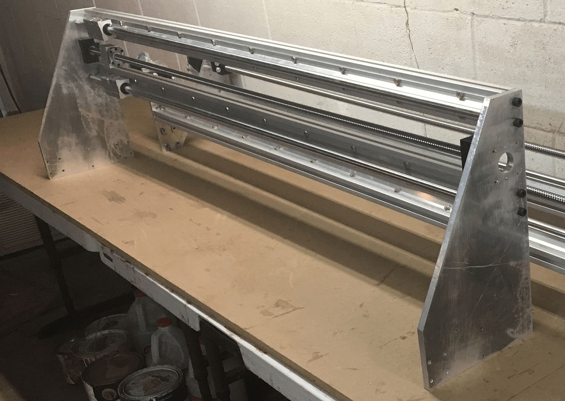
The framework is almost entirely aluminum extrusions and brackets by 80/20 Inc. The extruded profile is very strong for its weight and is easy to work with. We chose the 3030 series (30mm X 30mm), which works best for our requirements. We took the dimensions from our CAD model and simply went to work creating the base and table for the machine. We started with the custom machined end plates and built the gantry which determined the table width:
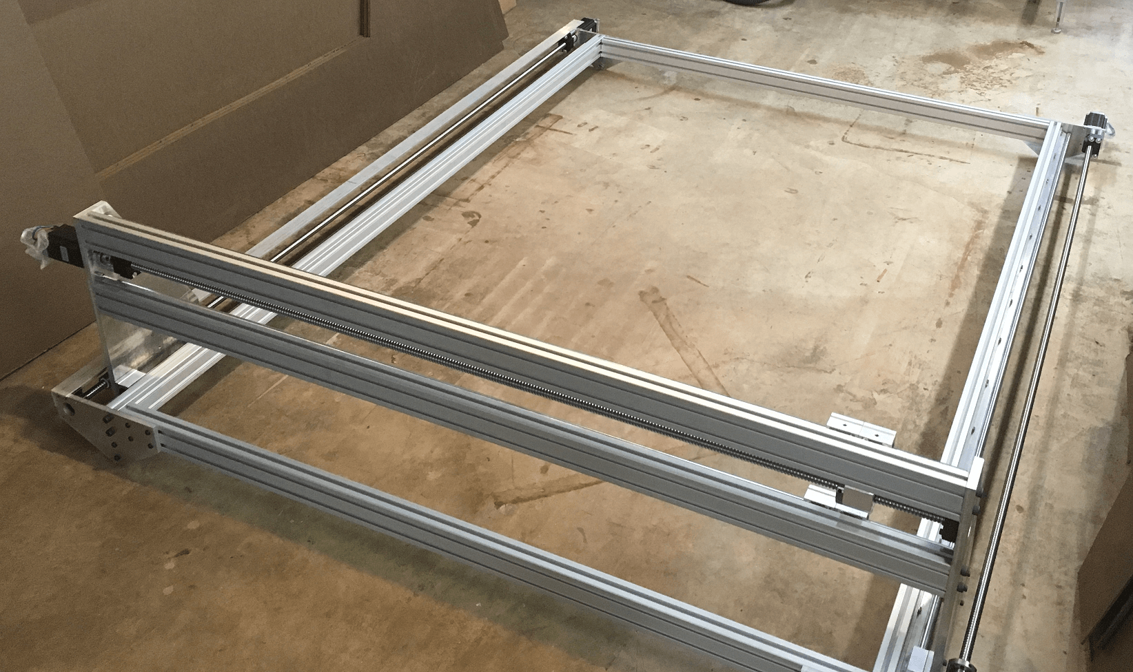
The next step was to layout and assemble the base of the table using the gantry to determine the width, and the Y-axis ballscrews to determine the length:
Then we added the legs and support structure:

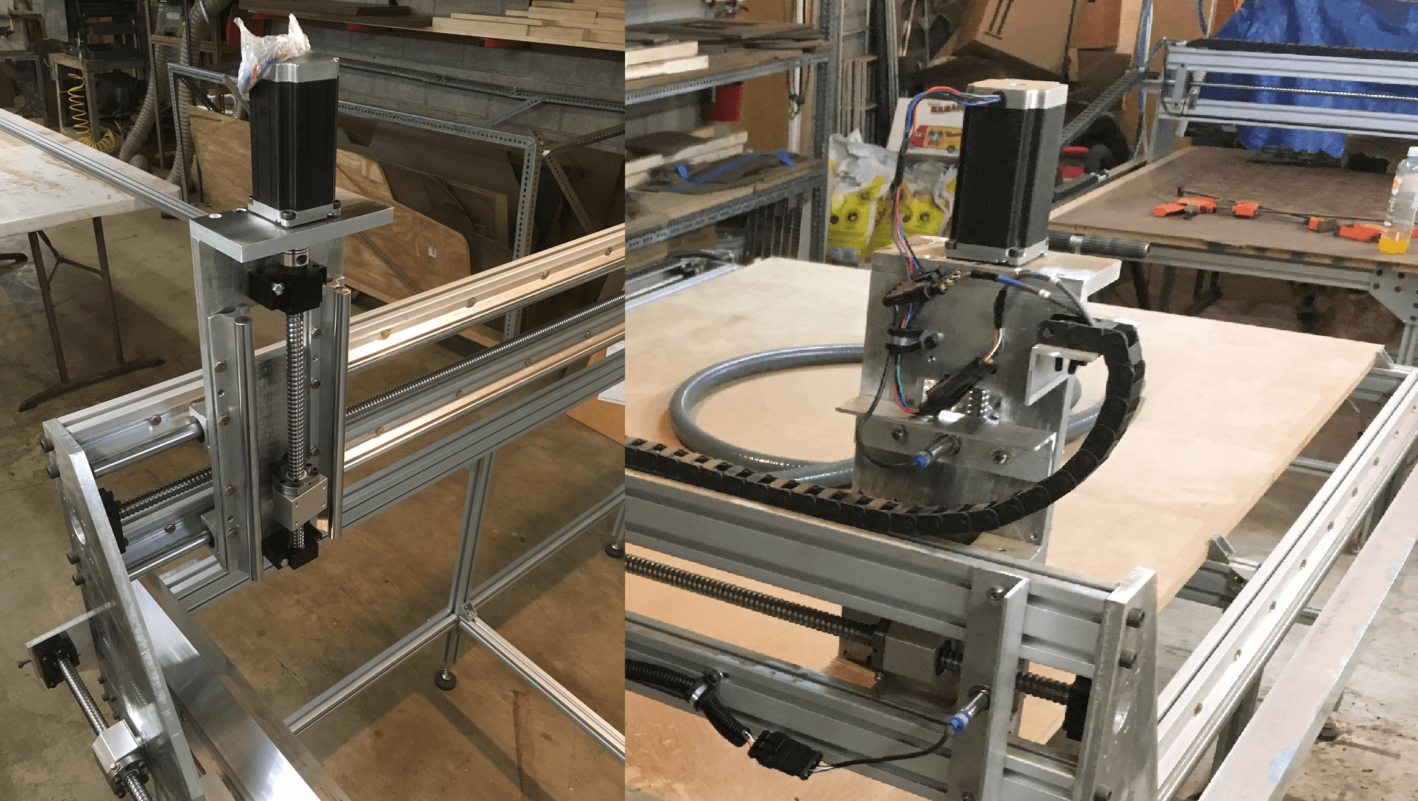
Finally we assembled the Z-axis:
Here is the layout we're going to use for this build:

Each motor (4 total) and each sensor (5 total) have a dedicated line to the control box. Because of the large size of the table, the Y-axis uses two motors, with one slaved to the other in the software. To keep it simple, we're going to use limit sensors on only one of the Y-axis. Although we will have to align the slaved axis manually in the initial setup, once configured it should rarely require adjustment (in an ideal world). However we will periodically check the alignment of the two in order to make sure they stay aligned and square.
Let's take a look at the wiring required for this setup, along with a few additions for safety and outputs so we can see what is powered up (status lights):

We won't go into too much detail on the actual wiring... there is plenty of information out there already about the details, and most motor/driver kits come with the necessary diagrams. There are two 120 VAC supplies to the our control unit, one for the internal power supplies and one for the spindle power supply. These are separately fused lines, and each has an on/off toggle switch on the front of the unit for manual override. The internal 12 VDC and 5 VDC power supplies derive their power from the same source as the 350W supplies, although this is not shown on the diagram and it would not have to be so. With these tied together however, the E-stop button will shut down the entire unit. The system is designed with three status lights: one for unit power, one for spindle power, and a third to indicate if the internal relay has been switched on to transmit power to the spindle (i.e. if the spindle is actually activated). The control unit incorporates an emergency stop button that cuts power to the entire system when manually engaged. The control box communicates with the computer via parallel cable. For the computer inputs, we chose a wireless keyboard and mouse so that no pendant controller is necessary (although they are readily available); the operator may carry the keyboard within a wide range of the machine for manual jogging and operation.
To make it easier on the eyes for layout, let's seperate what will be in the control box and what will be on the table of the machine:

The table wiring is fairly straightforward. Each sensor, motor, and spindle has a separate line that runs (through dragchain) along each axis until it gets to base of the table. We used connecting plugs at each motor or sensor to make part replacement easy if necessary instead of direct wiring. Each line terminates in an aircraft style connector at the control box so that they may be easily disconnected if necessary.
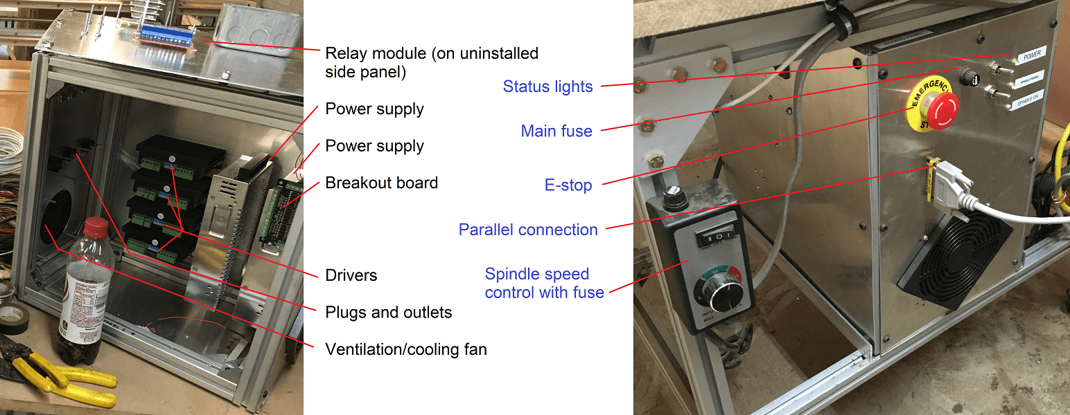
We made our control box frame out of 80/20 aluminum extrusions and brackets, then fabricated 1/16" aluminum plates to cover each side. The control box pulls in ventilation and cooling air from the rear through a filtered fan, and discharges out the front through another filter (to prevent backflow when the unit is off). Each panel is sealed with foam to the frame to prevent air leakage. We used T-slot nuts so any panel may be easily removed for access. Here is a picture of the box during assembly, and the front when mounted under the table:
This system works well when using a separate computer cabinet, as we are. We threw together a quick dust-proof cabinet to contain the computer and monitor, using the same ventilation and cooling system as the control box. Don't judge too harshly on our cabinet build... this was thrown together quickly from scrap materials we had lying around. There is only the parallel cable and a power cord running to the cabinet. The mouse and keyboard are wireless, although you can see a USB cord hanging on the side that we require to transfer machining files. Note the vintage swivel chair in pristine condition! (That chair has a history).

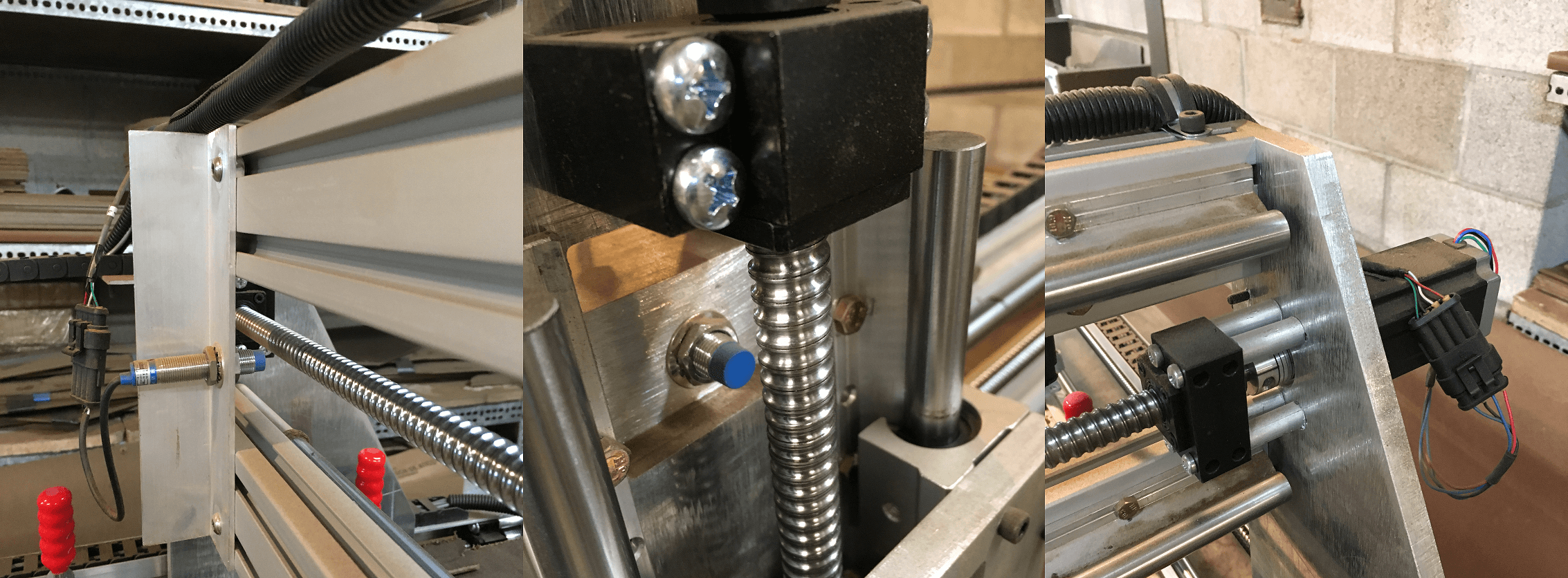
Here can be seen how we installed some of the proximity sensors, as well as the standard plugs we used for each mounted device:
This picture illustrates roughly how we ran the wiring and dragchain for this application, and the placement of the control box:
